By A Mystery Man Writer
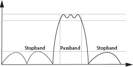
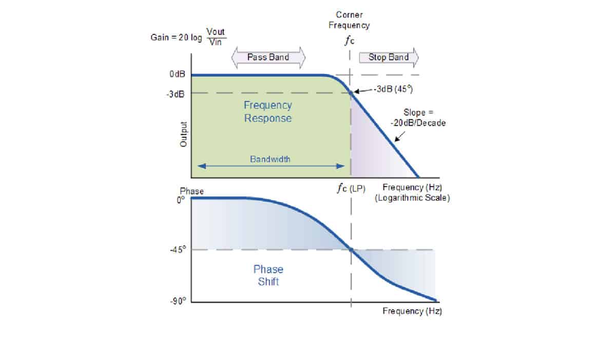
The Ideal Filter would have a unit gain (0dB) in its passband and a gain of zero (-infinity dB) in its stop band. Between the pass band and stop band, there would be no indecision and would transition from 0dB to -infinity dB asymptotically.
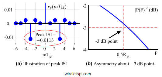
Pulse Shaping Filter

Knowles Precision Devices on LinkedIn: Know Today's RF Filtering Trends to Better Meet the Needs of Tomorrow's RF…

Knowles Precision Devices on LinkedIn: ⚠️Webinar Tomorrow⚠️ Don't forget to join us tomorrow for our webinar…
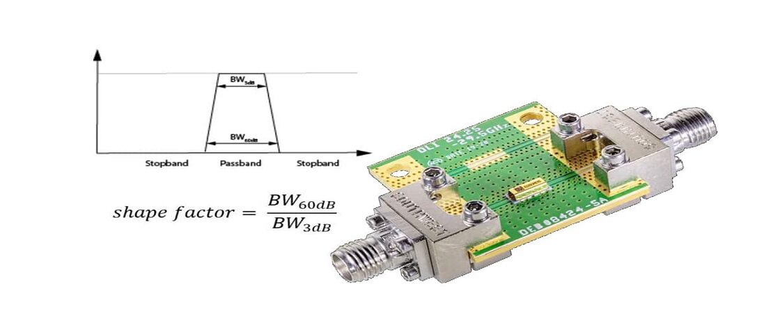
Filter Shape Factor and Selectivity

How to Design High-Selectivity Low-Distortion Filter Circuits

PPT - ECE 4990/5990 Design of RF Filters: Why we need filters PowerPoint Presentation - ID:3407707
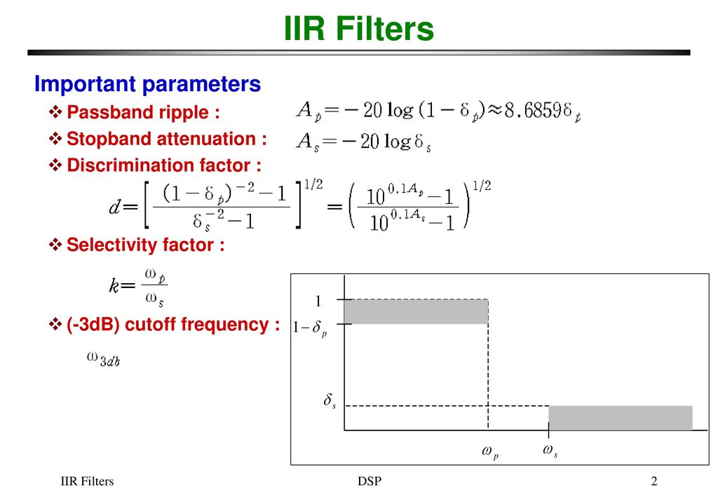
IIR Filters FIR vs. IIR IIR filter design procedure - ppt download
Contextualizing Q Factor
Understanding Selectivity

PDF] High-Selectivity On-Chip Optical Bandpass Filter With Sub-100-MHz Flat-Top and Under-2 Shape Factor

Knowles Precision Devices on LinkedIn: Know Today's RF Filtering Trends to Better Meet the Needs of Tomorrow's RF…

Filter Design Part 3. How Shape Factor, Insertion Loss, VSWR
How Passive Low Pass Filters Works